Author: Devika R
July 1, 2026
9 min read
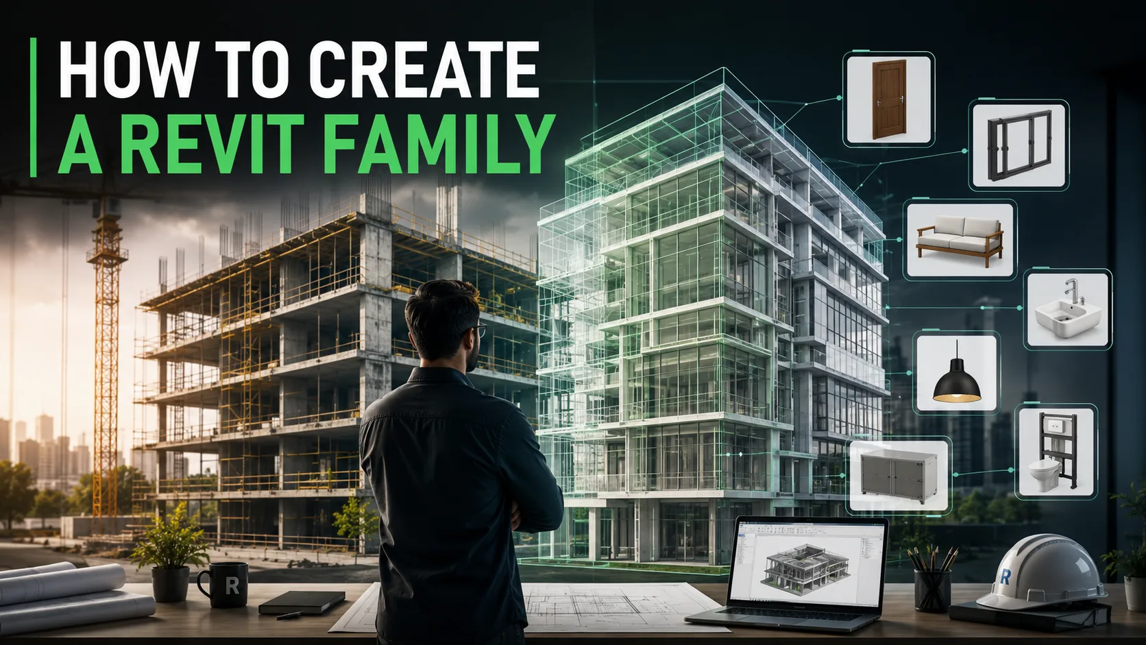
If you have spent any time in Revit, you already know the frustration: you need a specific door, a custom workstation, or a piece of equipment, and it simply is not in the default library. The fix is to build it yourself.
Learning Revit family creation is the moment most learners stop being “people who can open Revit” and start becoming BIM modellers who can deliver what a real project actually needs.
At BIM Cafe Learning Hub, family creation is one of the first hands-on skills we put students through on live project work, because almost every coordination problem, schedule error, or messy model can be traced back to badly built families. This guide walks you through how to create a Revit family from scratch, using a simple parametric table as a worked example, so you can follow the exact same logic for furniture, doors, windows, MEP components, or structural elements later.
1. What Is a Revit Family (and Why It Matters)
In Revit, a family is a group of elements that share the same behaviour and properties but can differ in size, material, or other parameters. A door family, for example, can contain a 900mm single door and a 1200mm double door — same logic, different values. Understanding families is not optional. Almost everything you place in a model belongs to one, which is why it sits at the core of every serious BIM workflow.
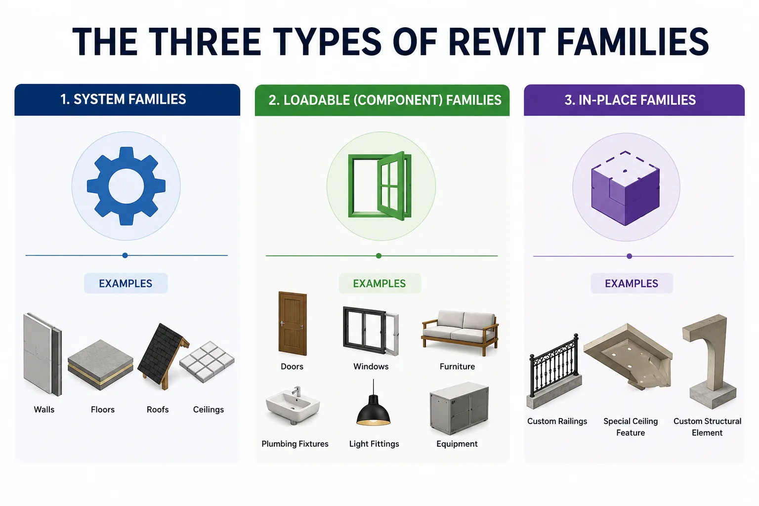
The three types of Revit families
- System families — built into Revit and tied to the project, such as walls, floors, roofs, and ceilings. You can duplicate and adjust them, but you cannot create or delete them from scratch.
- Loadable (component) families — the ones you build in the Family Editor and load into projects: doors, windows, furniture, plumbing fixtures, light fittings, and most equipment. This is where almost all custom family creation happens, and it is what this guide focuses on.
- In-place families — one-off elements modelled directly inside a project for a unique condition that will never be reused. Handy occasionally, but avoid them for anything repeatable, because they bloat the model.
For beginners, your time is best spent mastering loadable families. They are reusable, schedulable, and parametric — the three qualities that make a model genuinely useful.
2. Before You Start: What You Need
- A working installation of Autodesk Revit (any recent version — the workflow is almost identical across releases).
- Basic comfort with the Revit interface: the Ribbon, the Properties palette, and the Project Browser.
- A clear idea of what you are modelling. Sketch it on paper first and decide which dimensions need to flex.
That last point is the one beginners skip, and it is the most important. A family is only as good as the plan behind it. Before you draw anything, ask: which dimensions will users need to change, and which should stay fixed?
3. How to Create a Revit Family: Step by Step
We will build a simple parametric table where the length, width, and height can all be adjusted. The same nine steps apply to any loadable family you make later.
Step 1 — Start a new family and choose the right template
Go to File > New > Family. In the template dialog, pick the template that matches what you are building. For our table, choose Furniture.rft. If you were building a door, you would pick the door template; for a generic object, Generic Model.rft is a safe starting point.
The template matters more than it looks. It defines the family’s category, how it hosts (does it sit on a floor, a wall, or nothing?), and how it behaves when scheduled. Choosing the wrong template now causes problems later, so pick deliberately.
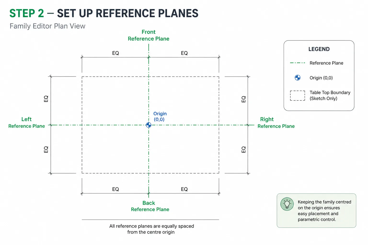
Step 2 — Set up reference planes
Reference planes are the invisible skeleton your geometry will hang from. On the Create tab, under the Datum panel, click Reference Plane and draw planes to mark the left, right, front, and back edges of your table top.
Use the aligned dimension tool to make the planes equidistant from the centre origin point. Keeping your family centred on the origin makes it far easier to place and host later. This skeleton is what keeps the family stable when dimensions change.
Step 3 — Add dimensions and turn them into parameters
Add aligned dimensions between your reference planes. With a dimension selected, use the Create Parameter button on the contextual ribbon to convert it into a parameter. Give it a clear name (Length, Width, Height) and choose whether it is a Type or Instance parameter.
- Type parameter — the value applies to every instance of that family type. Use this for most fixed dimensions.
- Instance parameter — the value can differ for each placed instance. Use this when users need to vary something on the fly.
Clean parameter names are not a cosmetic detail. On a coordinated project, vague labels like “Param1” cause real confusion when someone else opens your family two months later.
Step 4 — Build the geometry
Now create the actual 3D form. On the Create tab, the Forms panel gives you Extrusion, Blend, Revolve, Sweep, and Swept Blend. For a flat table top, Extrusion is perfect: sketch a rectangle and give it a thickness. For a tapered table stand, the Blend tool lets you transition between two different profiles.
Model what represents the object well — and nothing more. A common beginner trap is modelling every screw and bevel. That detail slows the whole project down once dozens of these families are loaded.
Step 5 — Lock geometry to the reference planes
This is the step that makes a family truly parametric, and the one most people get wrong. Use the Align tool (shortcut AL) to align each edge of your geometry to its matching reference plane, then click the small padlock icon that appears to lock it.
Once locked, the geometry follows the reference planes. Change a plane’s dimension and the table resizes with it. Skip the locks and your geometry will float free while the planes move — the classic “my family won’t flex” problem. If you want to work faster through steps like this, our guide to Revit keyboard shortcuts is worth keeping open beside you.
Step 6 — Flex the family
If the table resizes cleanly and holds its shape, your constraints are solid. If anything distorts or breaks away, go back, check your alignments, and confirm every lock is engaged. Flex early and flex often — catching a broken constraint now is far easier than after you have added materials and types.
Step 7 — Set the family category and add materials
Confirm the family category under Create > Properties > Family Category and Parameters (it should already read Furniture from your template). The category controls how the family schedules and filters in a project, so it has to be right.
Next, add a material parameter so the table’s finish can be controlled from inside the project rather than baked in. Assign a material, set its render appearance, and link it to a parameter. Now a user can switch the tabletop from oak to laminate without editing the family.
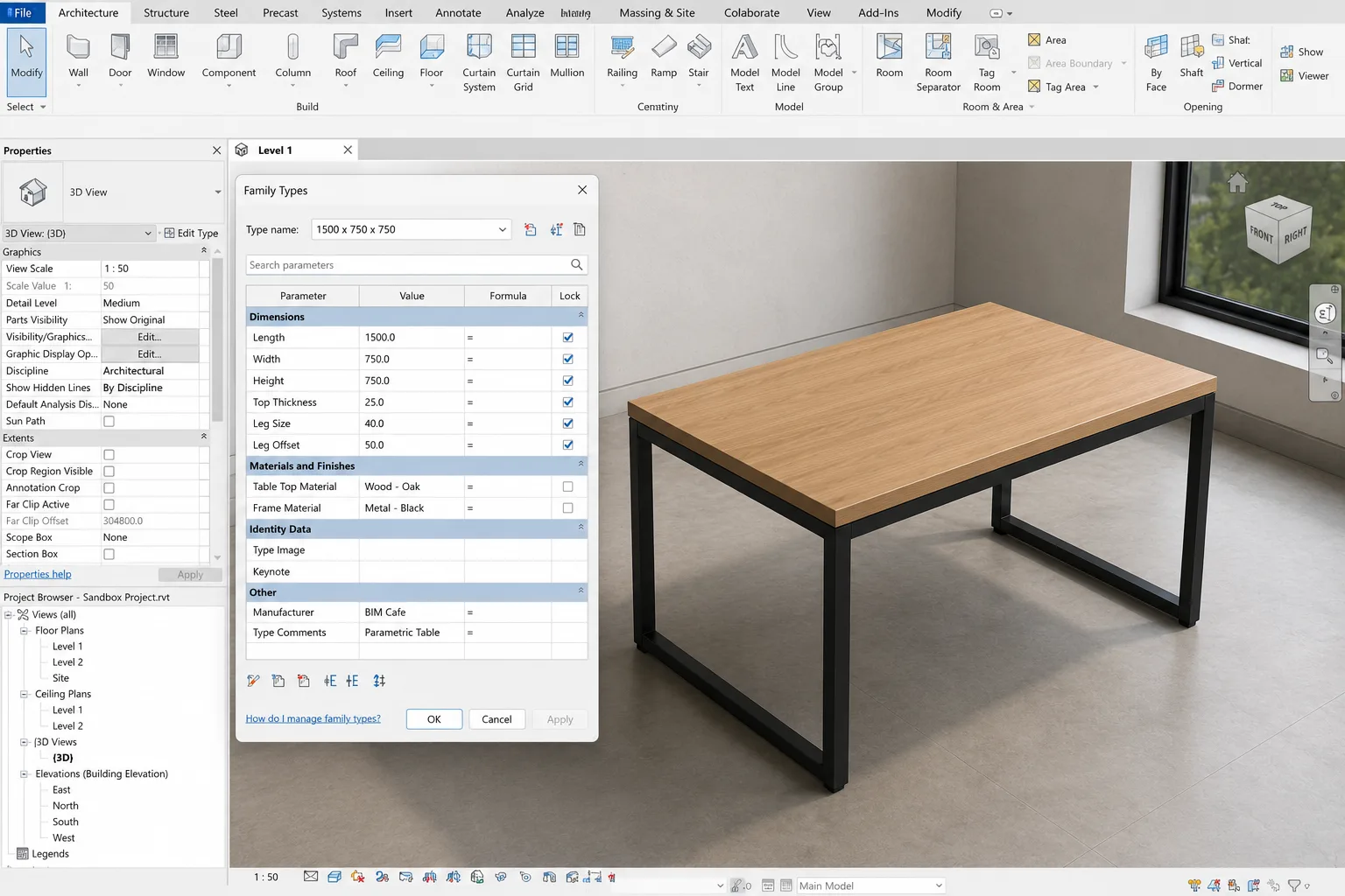
Step 8 — Create family types
In the Family Types dialog, create a few preset variations — say, a 1200mm, a 1500mm, and an 1800mm table. Each saved type stores its own set of parameter values. This is what lets one family serve many project needs from a single file. If you end up with more than six types, consider a type catalogue (a .txt file loaded alongside the family) to keep things manageable.
Step 9 — Load into a project and test
Open a blank project (or use a sandbox file), then click Load into Project. Place an instance, then test it properly: switch between your family types, adjust any instance parameters, and check both the plan and 3D views look correct.
Always test in a clean project before you trust a family on live work. If something behaves oddly, select the instance, click Edit Family, fix it, and reload. This loop — build, flex, load, test — is the heartbeat of all family creation.
4. Best Practices for Building Clean Revit Families
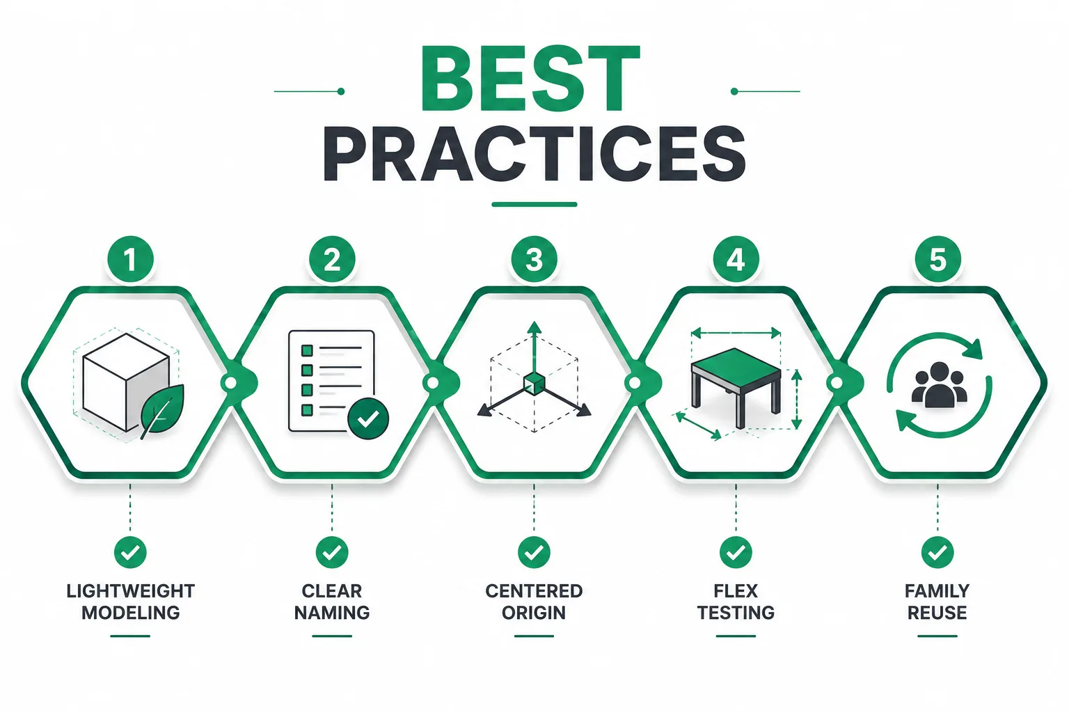
- Keep it lightweight. Model a good representation, not a perfect replica. Heavy families slow navigation, sync, and clash detection across the whole model.
- Name everything clearly. Parameters, reference planes, and types should be self-explanatory to the next person who opens the file.
- Centre on the origin. Families built around the origin host and place predictably.
- Flex before you finish. Test parameters at several values, not just one.
- Reuse, don’t rebuild. Start from a similar existing family or a clean template rather than downloading heavy, unverified families from random websites
5. Common Revit Family Creation Mistakes (and How to Fix Them)
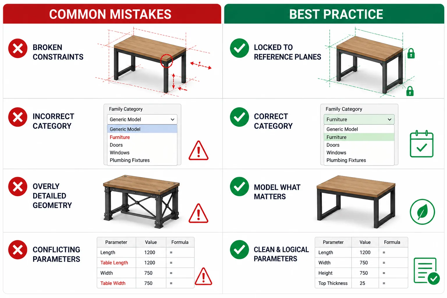
- The family won’t flex. Almost always missing locks. Re-align geometry to the reference planes and engage every padlock.
- Wrong category chosen. The family schedules incorrectly or won’t host. Reset it under Family Category and Parameters — but ideally pick the right template from the start.
- Over-modelled geometry. Strip out unnecessary detail to protect model performance.
- Parameters that fight each other. Plan your parameter hierarchy — primary dimensions first, dependent ones second, with formulas where needed (for example, a leg height of Height − Thickness).
These are the same slip-ups we see students make every batch. If you want a wider list of pitfalls to avoid as you learn the software, read our breakdown of common Revit mistakes.
6. How Family Creation Fits Into Real BIM Projects
On a real project, families are not a side skill — they are the difference between a model that coordinates and one that falls apart. Well-built parametric families schedule accurately, carry the right data for quantity take-offs, and behave predictably during clash detection. That data discipline is also tied directly to LOD (Level of Development): as a project moves from LOD 200 to LOD 350, your families have to carry more geometric and information detail.
This is exactly why employers across India and the Gulf value modellers who can build clean families rather than just place existing ones. It signals that you understand why an element is modelled a certain way, not just which button to press. If you want to see where Revit sits among the wider toolset, our guide to essential BIM software puts it in context.
7. Learn Revit Family Creation the Practical Way
Reading a guide gets you the logic. Building dozens of families on real, LOD-based project work gets you job-ready. At BIM Cafe Learning Hub, an Autodesk Authorized Training Centre in Kochi, family creation is built into hands-on assessments across our programs — not taught as theory.
If you are starting out, the Essential BIM Course covers family creation alongside core modelling. If you want full project depth with coordination and documentation, the Professional BIM Course takes you further with international LOD-based projects and placement support. Architects looking to specialise can explore the Architectural BIM & Design Development program.
Frequently Asked Questions
What is a family in Revit?
A family is a group of elements in Revit that share the same behaviour and parameters but can vary in size, material, or other properties — for example, a door family containing several door sizes. Families are the building blocks of every Revit model.
What are the three types of Revit families?
System families (built-in, like walls and floors), loadable or component families (custom-built in the Family Editor and loaded into projects), and in-place families (one-off elements made inside a single project). Most custom work involves loadable families.
Is it hard to create a Revit family?
A basic parametric family is beginner-friendly once you understand reference planes, parameters, and locking geometry. The logic stays the same as families get more complex, so mastering a simple example first makes everything afterwards easier.
Why won’t my Revit family resize when I change a parameter?
The most common cause is geometry that is not locked to the reference planes. Use the Align tool to align each edge to its plane and click the padlock to lock it, then flex the family again to confirm it resizes correctly.
What is the difference between a type and an instance parameter?
A type parameter applies the same value to every instance of that family type, while an instance parameter can be set differently for each placed instance. Use type for fixed dimensions and instance for values that need to vary per placement.
Can I learn Revit family creation online?
Yes. BIM Cafe Learning Hub offers online, offline, and hybrid Revit and BIM training where family creation is taught through hands-on, project-based assessments rather than theory alone.
Premium BIM Course
Professional BIM Course
Master BIM Course
Structural Design Concepts and BIM
Revit MEPF Master Course
Certified MEPF BIM Master Course
Electrical BIM Professional Program
RenderLab – Master 3D Modeling & Photorealistic Rendering
Multi-Tool Mastery for Architects & Engineers
BIM Coordinator Workflow Program
BIM FastTrack – 30 Day Intensive Training
Global Architectural & Structural BIM Project Program